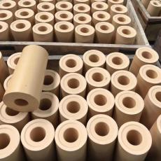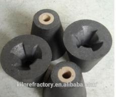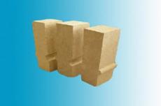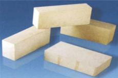
When casting refractory castable, the creation of expansion joints depends primarily on the following five key points:
01 Contraction and expansion of refractory castable
During the initial heating, refractory castable shrinks twice its volume during dehydration at 50°C - 200°C and during sintering at 900°C - 1000°C. At other temperatures, heating causes expansion. After the initial heating, the castable generally does not shrink any further. To prevent stress damage to the castable due to volume changes, the lining should be divided into small diagonal areas no larger than 1.5 m, poured in sections, and expansion and contraction spaces should be provided at the boundaries of each poured area.
02 Effect of expansion joints
The gap size should allow for free expansion of the castable in each section. Correctly located expansion joints can also serve as control joints. In high temperature areas (> 600 °C), the expansion joint width should be controlled within 3 to 4 mm, depending on the distance between the expansion joints. The expansion joint and control joint are located on the plane approximately 200 mm from the convex corner, but not in the convex corner or sharp cone. The cracking tendency of the castable on both sides of the expansion joint and control joint is relatively high, and the nail density can be increased accordingly.
03 Control of the expansion joint width
The expansion joint width depends on the operating temperature and the length of the control line. When the temperature is high and the control length is long, the expansion joint can be expanded accordingly. In relatively low temperature areas (< 400 °C), castable can be used directly on the equipment shell without insulation. Under these conditions, inserting 2mm thick cardboard or plastic film every 1.5m can satisfy the expansion space requirement.
04 Optimizing the location of the expansion joint
When determining the location of the expansion joint, reasonable attention should be paid to the vibration process. The vibration of the poured castable on one side of the gap should not affect the poured and vibrated castable that has begun to harden. The location of the expansion joint can avoid stressed parts, openings in the kiln body and lining. In areas with complex shapes such as corners, convexities, etc., expansion joints corresponding to their surfaces should be placed on convex corners and curved surfaces with small radii of curvature. Where two casting surfaces intersect to form a concave corner, an L-shaped expansion joint should be placed in this corner. The casting diagram should indicate the location and size of the expansion joints in the main parts. If the working temperature of the casting material exceeds 1200 °C, an expansion joint wider than 3 mm should be installed and a ceramic fiber blanket should be inserted.
05 Installing Control Joints
Since the casting material causes shrinkage cracks, it is necessary to install a control joint approximately 200 mm from the convex corner to ensure that shrinkage cracks can occur in a predetermined and safer place. The control joint can be filled with paper, paraffin or thin wood in a predetermined space. At high temperatures, flammable or liquid materials are poured. After these flammable materials are burned out or lost, the control joints are retained. The control joint should be installed in the middle of adjacent nails, at a practically equal distance from the nails on each side. It should be installed on continuous curved surfaces, conical surfaces and pipes, as well as on flat and curved surfaces where the risk of shrinkage cannot be controlled. It should be avoided in areas where expansion joints cannot be installed, such as small fill surfaces and convex corners.
